Connection of resistors experiment: measure with a voltmeter and ammeter in series and parallel connected resistors; voltages add up in series circuits, currents add up in parallel circuits; equivalent resistance calculation and mixed circuit
Interactively discover series, parallel, and complex connection types in electrical circuits with the connection of resistors simulation. In this experiment, you can measure current and voltage values using a voltmeter and ammeter, and practice equivalent resistance calculations. Designed in accordance with the high school physics curriculum, this tool allows you to grasp the fundamental laws in electrical circuits.
What can you do in this simulation?
You can observe the behavior of circuit components by setting up series and parallel connection types.
You can instantly measure voltage and current values with a voltmeter and ammeter.
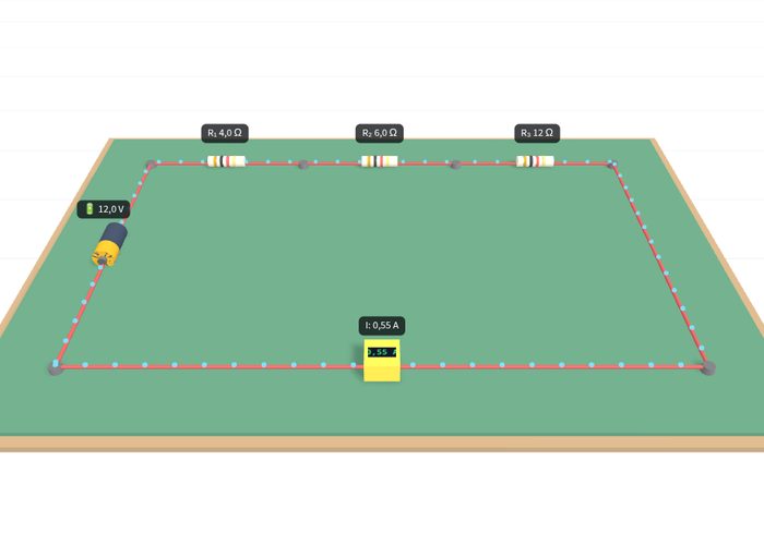
You can test equivalent resistance calculation by combining different resistance values (e.g., 4, 6, and 12 ohms) in complex circuit mode.
You can reinforce your theoretical knowledge with practice by answering guided questions.
Basic concepts and formulas
Resistors are connected in two main ways in electrical circuits. In the case of series connection, resistors are added end-to-end and the equivalent resistance (Req) is found by simple addition: Req = R1 + R2 + R3. In this connection, the current passing through the circuit is constant, while the voltage is shared across the resistors. In parallel connection, the ends of the resistors are connected to common points, and the equivalent resistance is calculated via the sum of reciprocals: 1 / Req = (1 / R1) + (1 / R2) + (1 / R3). According to Ohm's law (V = I · R), the relationship between voltage, current, and resistance is the primary reference in these connection types.
How to use?
Log in to the simulation panel and select the connection mode (series, parallel, or complex).
Place the appropriate resistance and voltage source values into the circuit.
Measure the current and voltage values in the circuit using the ammeter and voltmeter tools.
Perform equivalent resistance calculations and check your predictions with the experiment.
Complete the steps by answering the questions in the guide.
Frequently asked questions
Why is the current equal in resistors connected in series?
Since there is only a single branch in series circuits, there is no other path for electrons to follow; therefore, the exact same current passes through each resistor.
Why is the equivalent resistance in parallel-connected resistors smaller than the smallest resistance in the branch?
In parallel connection, new alternative paths are offered to the current, which increases the total conductivity of the circuit and ensures that the equivalent resistance turns out even smaller than the smallest resistance value in the branch.
How are complex circuits solved?
First, sub-groups that are clearly series or parallel within themselves in the circuit diagram are identified, and the circuit is simplified step by step by calculating the equivalent resistances of these sub-groups.
 Interactive experiment